The FASS
Titanium series designed for the 2005-2012 Dodge Cummins 5.9L/6.7 L and the
1998.5-2004 Dodge with in tank lift pump is available at Orange County Diesel
in Huntington Beach, California. If you have any questions about any other FASS
product, or if you need expert assistance installing your FASS Platinum, feel
free to call and speak to a FASS service professional at 714-848-2170.
This is Part 2
of a model-specific four-part series about how to install a FASS Platinum fuel
system.
Step 2: Prepare suction and return line.
Before removing the fuel tank, identify all areas of clearance between the tank and bed to install the draw tube assembly. The closer the suction tube is placed to the center of the fuel tank, front to back and left to right, the more usable fuel there will be.
 If more space is required to access the top of the fuel tank, loosen the strap nuts to the end of the stud. This will give you 3" more working room.
Remove the filler neck and overflow tubes from the truck by loosening the clamps at both ends.

Disconnect the factory suction and return line. The factory lines are removed by pressing in on the two tabs located in the connecting fuel line. Keep the tab on the factory return. Disconnect the factory electrical harness on top of the fuel tank. With the fuel tank empty of fuel, remove it from the vehicle.
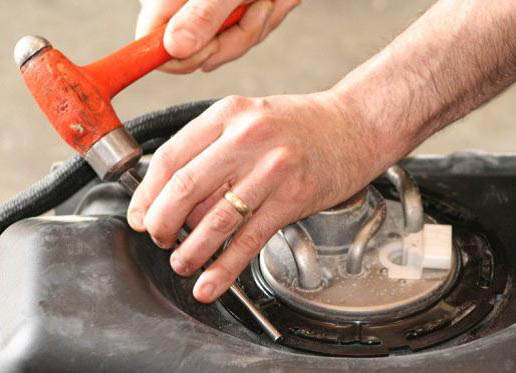
Clean the fuel module area then remove the lock ring on the top of the fuel tank.

Remove pick-up module from fuel tank once the lock ring is removed.

Assemble the BHF-1002 with the PL-1004 in ports "S" and "R" using thread tape, along with pushing the ST-1005P onto the barb portion of the BHF-1002. Insert O-ring into groove. Torque to 40 ft./lbs.
 Before drilling marked location, clean area of debris. Double-check area selected for any interference, including the fuel level arm.
 Drill a 1 1/2” hole, catching all debris. De-bur hole and remove any debris in the fuel tank.
 Support fuel tank on both ends to allow natural formation of the tank to take place. Failure to perform this step can and will create an issue with less usable fuel.
 Place the bulkhead assembly into the drilled hole. Take measurements so the bottom of the suction tube is only 1/8" from the bottom of the fuel tank. Using a razor knife, make multiple cuts to insure proper length. It is easy to shave the suction tube with the razor.
FY.I., it is more efficient to cut the tube too long and then correct to proper length than it would be when cut too short.
 With proper length obtained, place the assembly into the drilled hole, securing the assembly using the lock washer and nut. Torque nut. Loctite may be applied to the threads of the BHF-1002 for added insurance.
 Carefully re-install the install pick-up module. Make sure the leveling arm is not obstructed by the suction tube. Re-install factory lock ring.
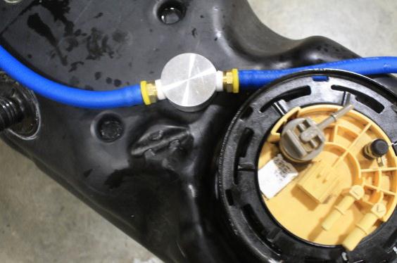
 Attach both end of the FL-1002 to the Push-Lok fitting of the BHF-1002. Remember to oil the fitting and fuel line. Route fuel line over frame rail when re-installing the fuel tank. Torque tank hanger bolts to proper specifications.
 Connect WH-1004 to the fuel module along with the factory fuel lines. Connect factory wire harness to the WH-1004.
 Re-attach filler neck and clamps.


FY.I., it is more efficient to cut the tube too long and then correct to proper length than it would be when cut too short.


No comments:
Post a Comment